The compressed-air system on trucks and buses: how it works
How trucks and buses make, dry, divide and store compressed air for brakes, suspension and gearshifts, what UN Regulation No. 13 requires of it, and how electric models drive the compressor.
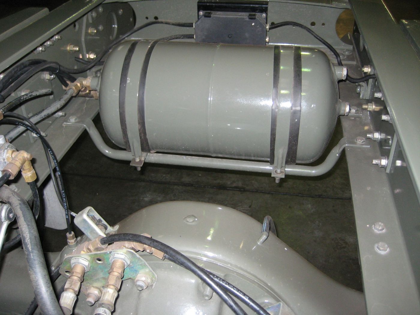
A truck or bus that brakes with air carries its own compressed-air plant. A compressor pressurises ambient air; an air dryer and an oil separator take out the water and compressor oil the air carries; a multi-circuit protection valve shares the air out between separate circuits; a reservoir on each circuit holds a reserve; and the service brakes, the spring parking brakes, the trailer and the auxiliary consumers draw on those reserves. UN Regulation No. 13, the braking regulation, describes the same chain in its own terms — an energy source, an energy transmission, reserves of energy — and sets what has to hold when part of it fails. On the battery-electric trucks and buses described in makers’ documents the air is still made on board, by a compressor driven by an electric motor of its own.
The chain at a glance
The table follows the air from intake to consumer. The component names are those used by the suppliers cited; a vehicle maker may use names of its own, as Volvo does (below).
| Stage | Component | What the source says it does | Source |
|---|---|---|---|
| Production | Compressor | Pressurizes ambient air “to power the vehicle’s on-board pneumatic equipment” | Knorr-Bremse |
| Pressure control | Governor and unloading mechanism | “maintains reservoir air pressure between a predetermined maximum and minimum pressure” | Bendix handbook (2000) |
| Treatment | Oil separator and air dryer | Separates oil “before the air is dried”; a “specialized granulate extracts the moisture” | Knorr-Bremse |
| Distribution | Four-circuit (multi-circuit) protection valve | “prioritizes compressed air distribution and secures the circuits” | Knorr-Bremse |
| Storage | Reservoirs (air tanks) | “a storage tank for a volume of compressed air”; the reservoirs of the different circuits must be easy to identify | Bendix handbook (2000); UN R13 Annex 7 |
| Use | Service and spring brakes, trailer, auxiliary consumers | Air goes “to the service brakes for the front and rear axle and trailers, to the park brake and auxiliary devices” | Knorr-Bremse |
Making the air: the compressor
Knorr-Bremse describes the compressor as the part that “pressurizes ambient air to power the vehicle’s on-board pneumatic equipment”, and names the piston compressor as “the most common design for heavy commercial vehicles”. Its piston range comes with different stroke volumes, in one- or two-cylinder form and with flange or foot mounting, and “as a rule, piston compressors are rigidly connected to the drive motor that powers them.”
None of the European documents cited here describes how the compressor is driven; the description comes from a North American source of 2000, Bendix’s Air Brake Handbook. It states that the air compressor is “the source of energy for the air brake system”, that it is “driven by the vehicle engine, either by belt or drive gear”, and that on most vehicles it uses the vehicle’s lubrication and cooling system, although self-lubricated and air-cooled compressors are available in some models. All Bendix reciprocating compressors, the handbook adds, have automatic inlet and discharge valves and an unloading mechanism. How the engine power regulation treats the brake air compressor on the test bench is set out in reading truck power figures.
UN Regulation No. 13 does not require more than one source of energy, but asks that it be driven safely. Paragraph 2.48 defines an energy source as “a device that both generates and provides energy required for the braking system”, and paragraph 5.2.1.5 states that “there need not be more than one supply (energy source or electrical supply, as relevant) of such energy (hydraulic pump, air compressor, etc.), but the means by which the device constituting that supply is driven shall be as safe as practicable.” Annex 7, Part A, sets a capacity requirement for the compressor as well, expressed as the time the pressure takes to rise in the least-favoured energy storage device; during that test the energy storage devices for auxiliary equipment are isolated. The text quoted throughout is the one published in the Official Journal on 13 April 2026, incorporating all valid text up to Supplement 1 to the 15 series of amendments.
When the reservoirs are full: governor, unloading and clutch
Bendix’s handbook describes the governor as operating “in conjunction with the compressor unloading mechanism”, maintaining reservoir air pressure “between a predetermined maximum and minimum pressure”. The two thresholds appear in the Regulation as data rather than as figures. For vehicles with compressed-air braking systems, paragraph 5.1.4.5.2 lists the compressor/unloader valve’s “Max. cut-out pressure” and “Min. cut-in pressure” among the pneumatic characteristic data, and paragraph 5.1.4.5.1 requires those data to be specified at the vehicle in a visible position in indelible form or made freely available in another way, for example in the handbook. The values are left blank in the Regulation, to be filled in for each vehicle. Annex 6 also provides for “systems not equipped with a governor (e.g., pressure-limited compressors)”.
Knorr-Bremse describes two ways of saving the energy a compressor absorbs when no air is needed. Its High Performance Energy Saving System (HP-ESS) “reduces fuel consumption when the compressor is not required to produce compressed air (off-load mode)”. Its compressor with clutch is disconnected altogether: it “can be decoupled from the drive motor as soon as sufficient compressed air is available”, with the coupling and decoupling managed by the company’s Electronic Air Control (EAC), and Knorr-Bremse adds that these idle phases also minimise oil carry-over into the compressed air system. The company’s air processing unit can start the saving itself: “when system pressure is reached, the APU can activate the compressor’s energy-saving function.”
Treating the air: drying, oil separation and regeneration
Compressing air makes water. In Knorr-Bremse’s words, “As the compressor forces the air into a smaller volume, the air gradually loses its ability to hold this water vapor. Compression therefore produces a significant amount of condensation.” The air “must be dried” to protect the system from corrosion or freezing, and the company’s service site adds that moisture collecting as water in a reservoir reduces its volume, “meaning less air pressure can be stored”. The dryer does this with “a specialized granulate” that extracts the moisture. Bendix’s handbook describes its dryer as “a desiccant type in-line filtration system that removes both liquid and water vapor from the compressor discharge air before it reaches the air brake reservoirs.”
Oil is the second contaminant. Knorr-Bremse states that the compressed air “contains residues of compressor oil”, that this oil “can damage the elastomers used in the various valves of the compressed air system”, and that its Oil Separator Cartridge separates liquid and gaseous oil from the compressed air “before the air is dried”.
A desiccant that has taken up water has to be dried out again, and three sources tie that to the compressor’s idle phase. Bendix: “The desiccant material is regenerative, in that its adsorptive properties are renewed each time the compressor is unloaded.” Haldex, describing its DRYest dryer in 2002: “When compressor cut-out is reached, dry air is allowed to flow back to regenerate the desiccant bed.” DAF’s bodybuilders’ guidelines of 2010 for the LF, CF and XF105 ask that the governor’s cut-out pressure be reached periodically “to allow the air dryer element to regenerate while the compressor is running unloaded”.
Where the dry purge air comes from, and when it flows, varies. ZF’s System Saver dryer range includes a type whose “internal purge volume does not use system air for regeneration” (System Saver 1200 Plus), one “for use with a dedicated purge volume reservoir” (System Saver P), and a sequential two-cartridge unit that “allows one to regenerate while the other continues to dry the air” (System Saver TWIN), the last “designed for compressors that operate almost continuously”. ZF’s air processing units offer “system regeneration or regenerated air from separate purge tank”. In Bendix’s 2000 range, the AD-SP dryer “uses a small amount of air from the supply and front axle (secondary) reservoirs to perform the purge function”.
Dividing the air: the multi-circuit protection valve
After the dryer the air is split. Knorr-Bremse’s description of the valve that does it reads: “The four circuit protection valve – or multi circuit protection valve – prioritizes compressed air distribution and secures the circuits. It distributes air to the service brakes for the front and rear axle and trailers, to the park brake and auxiliary devices. To do so, the relevant reservoirs are filled with compressed air until they reach their operating pressure.” Haldex’s application guide gives the outlets numbers: circuits 1 and 2, connections 21 and 22 on the quadruple-circuit protection valve, are allocated to the service brake, and connection 23 or 24 is the ancillary consumer circuit.
The Regulation’s requirements on separate circuits do not name the valve. Where the service braking force and transmission “depend exclusively on the use, controlled by the driver, of an energy reserve”, paragraph 5.2.1.2.7.2 requires “at least two completely independent energy reserves, each provided with its own transmission likewise independent”. Paragraph 5.2.1.5.1 adds that in the event of a failure in any part of the transmission, the feed to the part not affected “shall continue to be ensured” where it is needed to halt the vehicle with the residual or secondary braking performance, by devices that can be easily actuated when the vehicle is stationary or by automatic means. The valve appears by name only in the data list at 5.1.4.5.2, which asks for the “Four-circuit protection valve” and its static closing pressure.
A single valve does a similar job between two reservoirs. Bendix’s handbook describes the pressure protection valve as a normally closed valve “typically used to protect or isolate one reservoir from another, by closing automatically at a preset pressure”, and as “commonly used to delay the filling of auxiliary reservoirs until a preset pressure is achieved in the primary or braking reservoirs”. Haldex’s pressure protection valve “protects different parts of the pneumatic circuit, such as the braking system and air suspension.”
Suppliers also build dryer and protection valve as one part. Knorr-Bremse’s Air Processing Unit (APU) “combines all the functions of an air dryer and a multi-circuit protection valve in a single unit”, as a flanged solution or a compact monoblock; ZF’s mechanical air processing units integrate “air dryer and multiple circuit protection valve functions” and, in ZF’s words, “dry, clean, store and distribute the compressed air”. Electronic versions add control. Knorr-Bremse’s EAC “combines pneumatics with an intelligent control system” and “manages the supply to the brake circuits and thus to all other on-board consumers”, and the company states that this control “eliminates the need for dedicated compressed air storage for the trailer and parking brake”. Its explanation for the number of variants on the market is historical: “Control systems for compressed air-operated braking systems have grown organically over time. New functions have often required new system components. Country-specific stipulations have necessitated different system variants.”
Volvo’s air brake schematic for the North American VN, dated September 2025, lists among its parts an “Air compressor”, an “Air drier”, an “APM (Air Production Modulator)” and two air tanks, one for the front brake circuit and one for the rear. The legend does not describe what the APM does, and the document notes that “The APM (Air Production Modulator) can vary depending on the variant of the product.”
Storing the air: reservoirs
The Regulation makes the reservoirs compulsory and asks that they be told apart. Annex 7, Part A, paragraph 1.1.1: “Vehicles on which the operation of the braking system requires the use of compressed-air shall be equipped with energy storage devices (energy reservoirs)” of a prescribed capacity; paragraph 1.1.2: “It shall be possible to easily identify the reservoirs of the different circuits.” Paragraph 1.1.3 waives the capacity requirement where the braking system can achieve at least the secondary braking performance without any energy reserve. Paragraph 5.2.1.2.7.2 requires, in each service braking circuit, a device for draining and exhausting in at least one of the air reservoirs, “in an adequate and easily accessible position”.
Bendix’s handbook describes the reservoir as a storage tank “sized by the vehicle manufacturer to provide an adequate volume of air for use by the braking system and auxiliary control devices”, notes that “Generally, more than one reservoir is used in air brake systems”, and gives reservoirs a secondary function as “a location where the air heated by compression, may be cooled and the water vapor condensed.” Its safety valve “protects the air brake system against excessive air pressure buildup” and sits in the reservoir that the compressor discharge line is connected to.
What is stored has to be shown to the driver. Under paragraph 5.2.1.13.1, any vehicle with a service brake actuated from an energy reserve, where the secondary braking performance cannot be obtained without the stored energy, carries a warning device “in addition to an indication of the available energy (e.g. a pressure gauge) where fitted”. The warning is optical or acoustic, its optical signal is the red warning signal of paragraph 5.2.1.29.1.1, it comes on at the latest when the stored energy in any part of the system falls to the level the paragraph defines, and it is “directly and permanently connected to the circuit”. With the engine running, or during a run cycle of a vehicle propelled by an electric motor, and with no faults in the braking system, it gives no signal “except during the time required for charging the energy reserve(s) after each new engine start/run cycle”. Where an auxiliary source of energy is essential to the functioning of a braking system, paragraph 5.2.1.14 sets the size of the reserve by its purpose: if the engine stops, or the means by which the energy source is driven fails, the braking performance must remain “adequate to bring the vehicle to a halt in the prescribed conditions.”
Where the air goes
Downstream of the reservoirs, each circuit has its own consumers.
Service brakes
The front and rear brake circuits feed the service brakes through valves and, where the vehicle has EBS, electro-pneumatic modulators. Knorr-Bremse’s relay valve, “In reaction to an air pressure signal from a control valve”, accelerates brake actuation “by allowing for quick and precise control of a large volume of air”. On Volvo’s VN schematic the service brake components include a footbrake valve, an EBS control unit, EBS modulators for the front and rear axles, ABS solenoid valves, wheel speed sensors and the service brake cylinders.
An electronic braking system changes how the brakes are commanded, not where their force comes from. Paragraph 2.53 of the Regulation defines an Electronically controlled Braking System (EBS) as “a service braking system where the control is generating an electrical signal in the control transmission and electrical output signals to devices which generate actuating forces produced from stored or generated pneumatic energy.” Knorr-Bremse’s description follows the same split: a pedal travel sensor registers the braking demand, the control unit calculates the brake pressure for each axle, and the setpoints go over the brake system’s own CAN bus “to the electro-pneumatic modulators (EPM), which regulate the pressure precisely”. With ABS alone, “The braking action is still transmitted pneumatically”. The same company describes its brake control software as covering the interaction of service and continuous brakes “with retarders, exhaust flaps and electric motors”, the subjects of retarders and engine braking and regenerative braking in trucks and buses.
Spring brakes and the parking brake
The parking brake turns the logic round: air holds it off. Annex 8 of the Regulation defines spring braking systems as “braking systems in which the energy required for braking is supplied by one or more springs acting as an energy storage device (energy accumulator)”, and states that “The energy necessary to compress the spring in order to release the brake is supplied and controlled by the ‘control’ actuated by the driver”. Knorr-Bremse’s parking brake valve controls the parking and secondary braking system “by gradually reducing the pressure in the spring components of the spring brake actuator”, and a quick release valve in the supply to those spring components is, in its words, generally used “to accelerate the engagement of the parking brake”.
For power-driven vehicles with spring brakes, Annex 8 sets supply rules of their own. Paragraph 2.3.1: “The feed circuit to the spring compression chamber shall either include an own energy reserve or shall be fed from at least two independent energy reserves.” Paragraph 2.3.3: during re-charging of the braking system from zero pressure, the spring brakes “shall remain fully applied, irrespective of the position of the control device”, until the pressure in the service braking system is sufficient to ensure at least the prescribed secondary braking performance of the laden vehicle. Paragraph 2.1 keeps the two systems apart: “A spring braking system shall not be used as a service braking system”, although after a failure in part of the service braking transmission it may be used to achieve the prescribed residual performance, provided the driver can graduate its action.
The parking brake can be integrated into the air treatment unit. Knorr-Bremse offers “integration of the electronic or pneumatic parking brake into the EAC unit”, with the result, in its words, that “Pneumatic components no longer need to be installed in the driver’s cab”; it first offered its electronic parking brake as an integrated function of EAC in 2012, and has offered it as a stand-alone system since 2017. Volvo’s VN schematic lists an “HCU (Hand Control Unit) (handbrake)” alongside the rear spring brake cylinders.
The trailer
Two air lines connect a towing vehicle’s air system to a trailer’s: a supply line and a pneumatic control line, with an electric control line beside them on vehicles that have one. The connections are coupling heads, the term the Regulation uses; Knorr-Bremse’s English page calls them clutch heads and states that they “are generally color coded to indicate the connections for the supply air and control air lines.” Its trailer control valve “allows for graduated service braking of the towed unit, among other functions”.
The Regulation deals with those lines separately. Paragraph 2.5 states that “The control and supply lines between towing vehicles and trailers shall not be considered as parts of the transmission.” Annex 8, paragraph 2.3.1, lets the trailer supply line branch from the spring brake feed line only “under the condition that a pressure drop in the trailer supply line shall not be able to apply the spring brake actuators”. Where a power-driven vehicle is authorised to tow a trailer whose brake is controlled from it, paragraph 5.2.1.15 requires a device on the power-driven vehicle so that, if the trailer’s braking system fails or the air supply pipe to the trailer is interrupted, the power-driven vehicle can still be braked with the effectiveness prescribed for secondary braking. Volvo’s VN schematic lists an “eTPCM (electronic Trailer Protection Control Module)”. The trailer’s own braking requirements, the electric control line and trailer EBS are set out in trailer brakes and EBS.
Air suspension
Haldex’s guide states the rule first: “For safety reasons, the compressed air for the braking system must be kept separate and isolated from that of the air suspension.” For motor vehicles — “tractor units” in the guide’s wording — it lists suspension pressure equal to the brake pressure, and suspension pressure greater or smaller than the brake pressure, the case it marks “trucks and buses”. It then describes two ways of feeding the suspension. In one, the air is taken from the ancillary consumer circuit, connection 23 or 24, “after the quadruple-circuit protection valve, in which case the quadruple-circuit protection valve must be designed to give priority to filling brake circuits 21 and 22”. In the other — “In most instances, the air suspension system is provided with a higher pressure than the braking system” — “the compressed air is taken between the governor valve and the quadruple-circuit protection valve, and fed to the air suspension air tank through a pressure protection valve”. On trailers and semi-trailers, the guide adds, the air suspension “is supplied from the braking system supply line”. Volvo’s VN routing tables list an “Air supply from the APM (Air Production Modulator), P25 to the rear ECS”, the truck’s Electronically Controlled Suspension. How the suspension uses that air — levelling, raising and lowering, kneeling — is the subject of ECAS air suspension.
Gearbox and clutch
Knorr-Bremse’s servo shift module “provides pneumatic shifting force support for manual transmission”, and its electronic gearshift modules for automatic transmissions combine mechanical parts “such as a pneumatic cylinder” with electronic components such as solenoid valves; the same page describes the M-GSU, which “generates the forces and movements required using electronic actuators” instead. For the clutch, the company states that “The energy required to open and close the clutch is generated hydraulically, pneumatically, or electro-mechanically.” Its clutch booster “translates the pedal force proportionally using compressed air”, and its electro-pneumatic clutch actuator uses “Solenoid valves to supply air to and vent the actuation cylinder”. On its undated page, an electro-mechanical clutch actuator for automatic transmissions is described as being developed for series production, with “independence from any available compressed air supply in the target application” among its advantages. The gearbox side is covered in automated manual transmissions.
Bus doors and other consumers
Knorr-Bremse says pneumatic components “provide the force needed for individual processes like clamping disc brakes or opening and closing bus doors”, the valves regulating the air flow to dose the force. One North American transit-bus door actuator, Wabtec’s Vapor Pneumatic Differential Engine, “consists of two opposed cylinders of different diameters with pistons connected by a rack”, operated “by applying air to – or venting air from – the larger cylinder”. The same maker lists an electric door actuator beside it, the ETO, with a “High-torque, electric motor matched with an electronic controller”, and an “Electric outside sliding plug door system”, so a bus door is not air-operated by definition. What the regulation requires of the doors themselves is set out in bus doors and emergency exits.
Bendix’s handbook of 2000 also describes air-operated accessories from its own range: an air horn, and a fan clutch, “an air-operated, normally engaged, on-off clutch that controls the engine cooling fan”; a pressure reducing valve serves “an air operated accessory that requires less than system pressure for operation.” DAF’s 2010 bodybuilders’ guidelines place a body’s air consumers, on the CF75/85 and XF Series, on “the air distribution unit (A) of circuit 4”, a unit connected to “port 24 of the APU valve”.
Where such consumers share the braking system’s reserves, the Regulation calls them auxiliary equipment. Paragraph 2.55 defines auxiliary equipment as “the collective of systems, functions, or components, including those that are essential to the operation of the vehicle, that are supplied with energy from the same energy reserves as the braking system.” Paragraph 5.2.1.16 requires that its operation, “even in the event of damage to the source of energy”, cannot cause the reserves feeding the braking systems to fall below the warning level of paragraph 5.2.1.13, and Annex 8, paragraph 2.3.2, lets auxiliary equipment draw from the spring brake feed line only if its operation, “even in the event of damage to the energy source”, does not cause the spring brake actuators’ reserve “to fall below the level that allows them to be released”.
Battery-electric trucks and buses
A battery-electric vehicle has no combustion engine to drive a compressor, and the makers’ documents describe an electric compressor in its place. Daimler Truck’s release of 10 October 2023 on the Mercedes-Benz eActros 600 describes its front box as “a complex technology module with several control units, high-voltage components and an electric air compressor”. MAN’s manual for the eTGS and eTGX, with a copy deadline of April 2026, lists the air compressor among the consumers connected to the high-voltage distributors, beside the high-voltage heaters and the refrigerant compressor, and places it on one coolant circuit with the drive unit, the MCS charge unit cooling system, the voltage converter and the front radiator.
The suppliers’ products differ in type. Knorr-Bremse has developed “a screw-type compressor driven by an electric motor” for electric or hybrid vehicles with medium to high air requirements, giving city buses as an example, which “can be installed either on the roof or under the floor”; at IAA Transportation 2022 it also showed a rotary vane compressor with an electric motor for vehicles with medium to low requirements. ZF’s e-comp Scroll is an “electric air compressor designed to provide compressed air for medium and heavy-duty hybrid, battery-electric, and fuel-cell commercial vehicles”, which ZF describes as oil-free. Among its features ZF lists “remote pressure build-up independent of the main drive” and energy savings from “compressor shut off when no compressed air is required”.
In the suppliers’ descriptions the air treatment remains, and its control electronics also run the compressor. ZF’s Air Supply Unit combines the e-comp Scroll “with ZF’s air processing technology, including SAPAC air management software”, and ZF states that the scroll principle “eliminates the need for oil lubrication”. Knorr-Bremse’s intelligent Air Processing Unit (iAPU) for electric buses has “intelligent regeneration” and, according to the company’s 2022 release, “also controls the electric motors in the screw-type and rotary vane compressors”; its GSAT platform lists the “Control of traditional compressors and compressors operated by electric motors”. Knorr-Bremse’s valve page makes the wider point that pneumatic components are used to activate individual vehicle processes “even in electric vehicles”.
The Regulation’s wording allows for such vehicles. Paragraph 5.2.1.5 speaks of a supply that may be an “energy source or electrical supply, as relevant”, and the warning device of 5.2.1.13.1 is described for a vehicle whose engine is running “or during a run cycle (e.g., in case of a vehicle propelled by an electric motor)”. Service contracts for electric trucks are a separate subject, set out in electric truck maintenance compared with diesel.
Quick answers
- What does the four-circuit protection valve on a truck do?
- It shares the compressed air out between separate circuits. Knorr-Bremse describes the four-circuit, or multi-circuit, protection valve as prioritizing compressed air distribution and securing the circuits: it distributes air to the service brakes for the front and rear axle and trailers, to the park brake and to auxiliary devices, filling the relevant reservoirs until they reach their operating pressure. UN Regulation No. 13 names the valve in paragraph 5.1.4.5.2, which lists its static closing pressure among the data required for compressed-air braking systems.
- Why does a truck's air system need an air dryer?
- Because compressing air produces water. Knorr-Bremse states that as the compressor forces air into a smaller volume it loses its ability to hold water vapour, so compression produces a significant amount of condensation, and that the air must be dried to protect the system from corrosion or freezing. In Bendix's 2000 handbook the dryer's desiccant is regenerative: its adsorptive properties are renewed each time the compressor is unloaded.
- How do spring brakes use compressed air?
- Air releases them; springs apply them. UN Regulation No. 13, Annex 8, defines spring braking systems as systems in which the energy required for braking is supplied by one or more springs acting as an energy store, and the energy needed to compress the spring in order to release the brake is supplied and controlled by the driver's control. Knorr-Bremse's parking brake valve controls the parking brake by gradually reducing the pressure in the spring components of the spring brake actuator.
- Do battery-electric trucks and buses still have an air compressor?
- The ones described in makers' documents do, driven by an electric motor of its own. Daimler Truck's release of 10 October 2023 lists an electric air compressor in the front box of the Mercedes-Benz eActros 600, and MAN's eTGS and eTGX manual (04/2026) names the air compressor among the consumers connected to the high-voltage distributors. Knorr-Bremse offers electrically driven screw and rotary vane compressors, and ZF an electric scroll compressor.
- What does UN Regulation No. 13 require of the air supply?
- One source is enough, but the reserves must hold. Paragraph 5.2.1.5 allows a single supply such as an air compressor, driven as safely as practicable; where an auxiliary energy source is essential to braking, paragraph 5.2.1.14 requires a reserve that still brings the vehicle to a halt if the engine stops or the energy source's drive fails; Annex 7 requires reservoirs whose circuits can be easily identified; and where service braking depends exclusively on stored energy, paragraph 5.2.1.2.7.2 requires at least two completely independent energy reserves.
Models in this article
Sources
- UN Regulation No. 13 — Uniform provisions concerning the approval of vehicles of categories M, N and O with regard to braking [2026/746], incorporating all valid text up to Supplement 1 to the 15 series of amendments — Official Journal of the European Union, L series 2026/746 of 13 April 2026, 13 Apr 2026
- Compressors – pressurizing air for commercial vehicles — Knorr-Bremse
- Compressed Air Systems – Essential for Pneumatic Performance (air treatment) — Knorr-Bremse
- Conventional Air Treatment: air dryers, APUs and multi circuit protection valves — Knorr-Bremse TruckServices
- GSAT: Global Scalable Air Treatment — Knorr-Bremse
- Compressed air valves: Pneumatic components for brake and air spring systems — Knorr-Bremse
- Electronic Braking Control: EBS and ABS for truck, bus and trailer — Knorr-Bremse
- Electronic Parking Brake (EPB) — Knorr-Bremse
- Transmission Actuation — Knorr-Bremse
- Clutch Actuation — Knorr-Bremse
- Buses – Carrying the most important cargo — Knorr-Bremse
- Knorr-Bremse showcases cutting-edge traffic safety technologies at IAA TRANSPORTATION 2022 (press release, Munich, 19 September 2022) — Knorr-Bremse AG, 19 Sept 2022
- Mechanical Air Processing Units: C-APU and M-APU — ZF Friedrichshafen AG
- Mechanical Air Processing Units: System Saver air dryers — ZF Friedrichshafen AG
- e-comp Scroll electric air compressor — ZF Friedrichshafen AG
- Air Supply Unit: an all-in-one air management solution for electrified and hybrid commercial vehicles — ZF Friedrichshafen AG
- Body Builder Instructions, VN (4), Section 5: Air Brake System Schematics and Routing (Date 9.2025) — Volvo Trucks North America
- Trailer application guide: Air suspension, system description — Haldex
- Trailer application guide: Pressure protection valve — Haldex
- DRYest Air Dryer, Installation and Maintenance, L31166 (9/02): product description — Haldex
- Bodybuilders' Guidelines DAF LF, CF and XF105, update 2010-04: section 6.10, Compressed air system — DAF Trucks N.V.
- The Air Brake Handbook, BW5057 (8/2000), copy in NHTSA investigation file PE20003 — Bendix (Honeywell Commercial Vehicle Systems), hosted by the US National Highway Traffic Safety Administration
- Mercedes-Benz Trucks celebrates world premiere of the battery electric long-haul truck eActros 600 (press release, 10 October 2023) — Daimler Truck AG, 10 Oct 2023
- Manual: Breakdown assistance, towing, recovery — eTGS and eTGX (publication 803808, copy deadline 04/2026), high-voltage components and thermal management — MAN Truck & Bus SE
- Pneumatic Differential Engine (transit bus door actuator) — Wabtec Corporation