operating
Trailer brakes and EBS: what the rules require of an O3 or O4 semi-trailer
Continuous braking, anti-lock and a pressure test connection downstream of the control line coupling head: what UN Regulation No. 13 asks of a heavy trailer, and why a mismatched pair brakes badly.
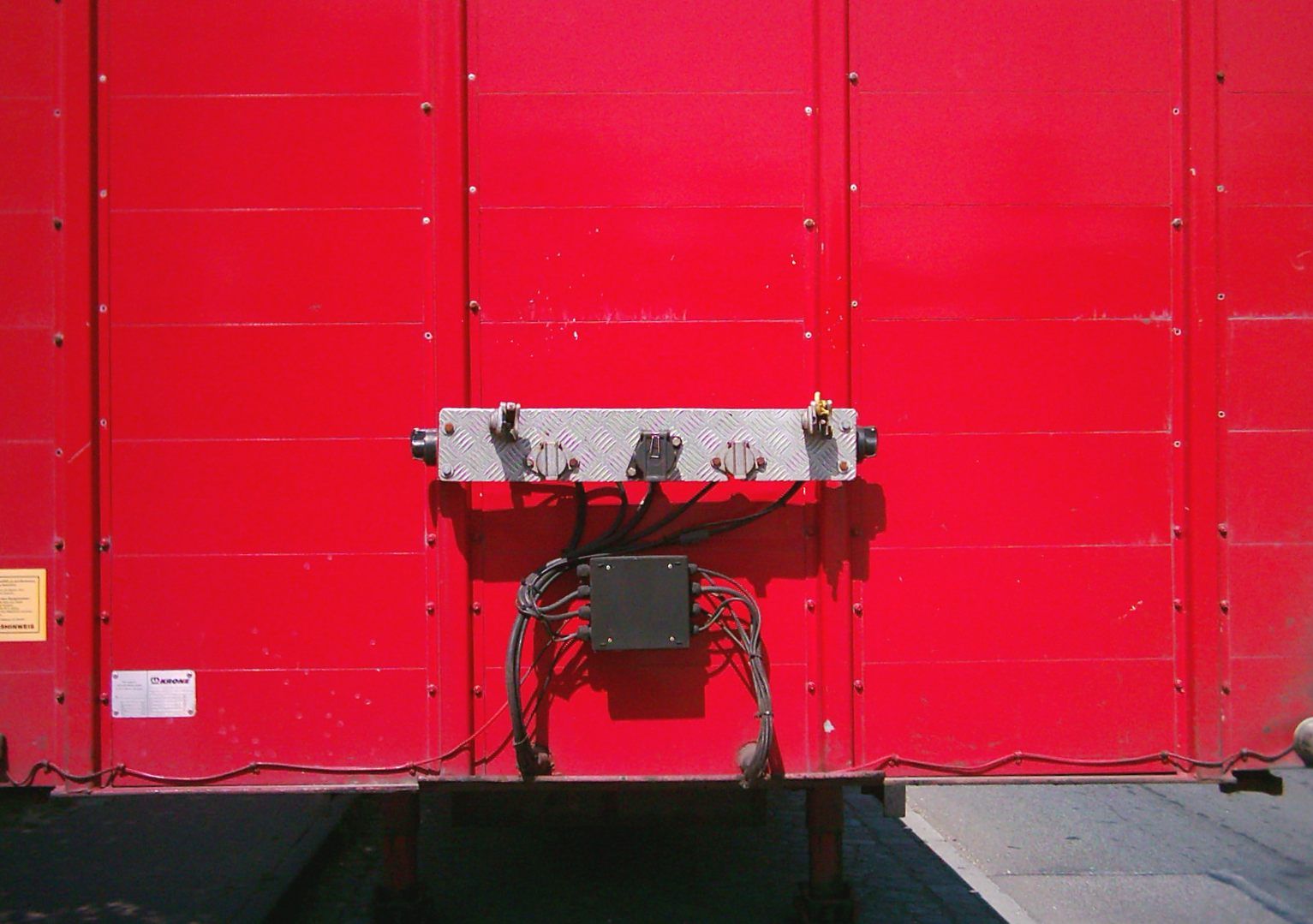
A heavy trailer’s braking system is approved on its own, and so is the tractor’s. No approval certifies a particular pairing, and neither file tells you how a given tractor and a given trailer will divide the work between them. That is the fact underneath most of what a mixed fleet experiences as a trailer that brakes late or a tractor that does all of it.
O3 and O4 are mass bands, not trailer types
Regulation (EU) 2018/858 sets the categories. Article 4(1)(c) divides category O into O1, trailers with a maximum mass not exceeding 0,75 tonnes; O2, exceeding 0,75 tonnes but not exceeding 3,5 tonnes; O3, exceeding 3,5 tonnes but not exceeding 10 tonnes; and O4, exceeding 10 tonnes.
The figure is not the combination’s, which is the separate question of truck weights, GVW and GCW — but on a semi-trailer it is not the gross trailer mass either. Article 4(2) sends the categorisation criteria to Annex I, and point 2.2.3 of that annex states that in the case of a semi-trailer, a centre-axle trailer and a rigid drawbar trailer, the maximum mass to be considered for classifying the vehicle corresponds to the maximum mass transmitted to the ground by the wheels of an axle or group of axles when coupled to the towing vehicle. The share resting on the tractor through the kingpin and fifth wheel is outside it. Almost anything a European operator would call a semi-trailer is O4 all the same: the band opens above 10 tonnes and has no upper end. Body type does not enter into it, so a curtainsider, a tanker and a low-loader are one category here, and what separates them belongs to trailer types.
The braking rules are not EU rules in origin. Annex I of Regulation (EU) 2019/2144, consolidated to 2 August 2026, lists UN Regulation No. 13, “Braking of vehicles and trailers”, at the 11 series of amendments published in OJ L 42 of 18 February 2016, for categories M2, M3, N and O.
What the regulation requires the trailer to carry
Paragraph 5.2.2.3 is the whole of the service braking requirement: trailers of categories O3 and O4 shall be equipped with a service braking system of the continuous or semi-continuous type. Both are defined at 2.9 and 2.10 and describe the combination rather than the trailer: a single control the driver actuates progressively, and simultaneous or suitably phased braking of every constituent vehicle whatever their relative positions. What they exclude is inertia braking, which 5.2.2.2 permits only for centre-axle trailers in category O2. A heavy trailer may not brake because it has run up on the tractor.
The system shall act on all the wheels and distribute its action appropriately among the axles (5.2.2.4); the trailer shall stop automatically if the coupling separates in motion (5.2.2.9); and parking braking shall be assured even when the trailer is separated from the towing vehicle, actuable by a person standing on the ground — or, on a trailer used for the carriage of passengers, from inside the trailer (5.2.2.10).
Anti-lock is not optional at this weight. Paragraph 5.2.2.13 requires an O3 trailer to have an anti-lock braking system in accordance with Annex 13, and an O4 trailer one in accordance with the category A requirements of Annex 13. Stability control is drawn more narrowly, and with more qualifications than a summary usually carries. Paragraph 5.2.2.23 opens “subject to the provisions of paragraph 12.3 of this Regulation” — the transitional provision under which approvals to the preceding series had to be accepted until 1 September 2026 — and then requires a vehicle stability function, including at least roll-over control and meeting Annex 21, on vehicles of categories O3 and O4 having no more than three axles and equipped with air suspension. Footnote 27 takes two classes straight back out: trailers for exceptional load transport and trailers with areas for standing passengers are excluded from the requirement. A three-axle air-suspended low-loader satisfies the two conditions and is still outside the rule.
Because 5.2.2.13 gives every O3 and O4 trailer an anti-lock system, every one of them also falls inside 5.2.2.17, which requires a connector conforming to ISO 7638:2003, an automated connector meeting Annex 22, or both. The same paragraph adds a marking worth checking on a trailer equipped with the ISO 7638:2003 connector: it shall be marked in indelible form to indicate the functionality of the braking system when that connector is connected and disconnected, positioned so as to be visible when the pneumatic and electrical interface connections are made.
The test connection is the thing to look for
Paragraph 5.2.2.12 is the most useful line in the regulation for anyone auditing a trailer. Trailers of categories O3 and O4 shall satisfy paragraph 5.2.1.18.4.2, and an easily accessible pressure test connection is required downstream of the coupling head of the control line.
The cross-reference gives that tapping its meaning. Paragraph 5.2.1.18.4.2 requires that when the supply line is evacuated at the rate of at least 100 kPa per second, the automatic braking of the trailer shall start to operate before the pressure in the supply line falls to 200 kPa — a defined rate and a defined pressure rather than “eventually”. The next sub-paragraph then qualifies it. Under 5.2.2.12.1, a trailer other than a towing trailer that has an electric control line and is electrically connected to a towing vehicle with one may suppress that automatic braking action, as long as the pressure in its own compressed air reservoirs is sufficient for the performance of Annex 4 paragraph 3.3 — not less than 13.5 per cent of the maximum stationary wheel load, tested laden from 40 km/h. On the combinations this article is about, the permission is the ordinary case, not an edge case.
The test point sits on the control line just past the coupling head, so the pressure arriving from the towing vehicle can be read at the boundary between the two vehicles without dismantling anything. That boundary is what Annex 10 is about: its paragraph 1.3.1 requires at least one axle to commence developing a braking force when the coupling head pressure is within 20 to 100 kPa, laden and unladen.
A used buyer cannot repeat that test in a yard, but can confirm the connection is present, unobstructed and reachable. It is not the only tapping the regulation asks for — paragraph 5.1.4.2 requires further air pressure test connections for the purpose of periodic technical inspection, among them one in each independent circuit so that the input and output pressure of the complete transmission line can be checked (5.1.4.2.4), all of them complying with clause 4 of ISO 3583:1984. What makes a buried test point a defect rather than a nuisance is 5.1.4.3: the accessibility of required pressure test connections shall not be obstructed by modifications and assembly of accessories or the vehicle body.
| Figure | Paragraph | What it fixes |
|---|---|---|
| 650–850 kPa | Annex 10, 3.1.3.1 | At the supply and control line coupling heads at full application, whatever the load, on a vehicle authorised to tow O3 or O4 trailers — tested with the energy source stopped, the supply line blocked off and a 0.5 litre reservoir on the pneumatic control line |
| 650–850 kPa equivalent | Annex 10, 3.1.3.2 | The same window, as a digital demand value on the electric control line |
| 20 to 750 kPa | Annex 10, 3.1.6.3 and 4.1.1 | Range over which the compatibility bands are plotted |
| 20 to 100 kPa | Annex 10, 1.3.1 | Coupling head pressure at which one axle must begin to brake |
| 200 kPa | 5.2.1.18.4.2 | Supply line pressure above which automatic braking must have started, unless suppressed under 5.2.2.12.1 |
| 0.4 second | Annex 6, 3.5.1, 3.5.2 and 3.5.3 | Trailer response time limit, the two control lines determined independently |
Why a mismatched pair brakes badly
Annex 10’s compatibility requirements are bands rather than points. A tractor for semi-trailers must keep the relationship between its braking rate and the control line pressure inside the areas shown on diagram 3, for all pressures between 20 and 750 kPa (3.1.6.3). A semi-trailer must do the same for its own braking rate against that pressure, inside two areas derived from diagrams 4A and 4B (4.1.1).
Both requirements are then loosened for exactly the vehicles this article is about. Paragraph 1.1(b) drops the unladen half for towing vehicles and trailers with a compressed air braking system that are equipped with an anti-lock system fulfilling Annex 13 — which 5.2.2.13 makes every O3 and O4 trailer — leaving in its place the rule that for all load conditions a braking rate shall be developed between 20 kPa and 100 kPa at the coupling head of the control line. And 4.1.1 does not have to be fulfilled at all by a semi-trailer with a Kc factor of less than 0.95 that meets at least the braking performance of Annex 4 paragraph 3.1.2.1 or 3.1.3.1, as appropriate (4.1.2).
Nothing in that structure asks the two vehicles to be matched to each other. Each is proved alone against its own diagram, and the regulation is explicit that the tractor’s proof is done uncoupled: the 650 to 850 kPa full-application values of 3.1.3.1 and 3.1.3.2 shall be demonstrably present in the power-driven vehicle when uncoupled from the trailer (3.1.3.3). Two vehicles can each sit legally inside their band while sitting at opposite edges of it. At the same control pressure one pair has the trailer doing more of the work and another has the tractor doing more, both fully approved.
Response times are established the same way. Annex 6 paragraph 3.1 requires a trailer’s response times to be measured without the power-driven vehicle, against a simulator to which the coupling heads of the supply line, the pneumatic control line and/or the connector of the electric control line are connected. Each side is timed on its own bench.
The regulation puts the correction on the towing vehicle. Coupling force control shall only be permitted on the power-driven vehicle (5.2.1.28.1), and its action shall be to reduce the difference between the dynamic braking rates of power-driven and towed vehicles (5.2.1.28.2). That same paragraph is where a coupled pairing comes closest to reaching the paperwork: the operation of the coupling force control shall be checked at the time of type approval, by a method agreed between the vehicle manufacturer and the technical service, with the method of assessment and the results appended to the type approval report. A tractor can pull a strange trailer into line to a degree. A trailer cannot do the same for a strange tractor.
Two control lines, and which one the trailer obeys
Paragraph 5.1.3.1 allows three arrangements: one pneumatic supply line and one pneumatic control line (5.1.3.1.1); those two plus an electric control line (5.1.3.1.2); or a pneumatic supply line and an electric control line alone (5.1.3.1.3). The third is barred by footnote 4, which says that until uniform technical standards have been agreed which ensure compatibility and safety, connections between power-driven vehicles and trailers conforming to 5.1.3.1.3 shall not be permitted. That leaves two lawful arrangements, not one. The ISO 7638 connector of 5.2.2.17 does not close the gap either, because Annex 16 paragraph 1.2 treats it first as a power supply for the braking or anti-lock system, which also provides a data communication interface via pins 6 and 7 only on a vehicle equipped with an electric control line. In practice a modern heavy trailer is built to 5.1.3.1.2 and carries both — but that is a market observation, not something the footnote decides.
Where both vehicles do carry two control lines, 5.1.3.4 settles which one governs. Both signals shall be present at the coupling head, and the trailer shall use the electric control signal unless it is deemed to have failed, in which case it automatically switches to the pneumatic line (5.1.3.4.1). Each vehicle shall conform to Annex 10 for both lines (5.1.3.4.2), but Annex 10 paragraph 1.2 adds that identical braking characteristic curves for the two are not required. That sentence explains why a combination can feel different once a fault has dropped it back to the pneumatic line, with nothing out of specification. On a failure within the electric control transmission, at least 30 per cent of the trailer’s prescribed service braking performance has to be maintained (5.2.2.15.2).
This is where the marketing word meets the regulation, and the answer depends on which edition you open. The text at OJ L, 2026/746 defines it: paragraph 2.53 makes an Electronically controlled Braking System (EBS) a service braking system where the control is generating an electrical signal in the control transmission and electrical output signals to devices which generate actuating forces produced from stored or generated pneumatic energy. The phrase appears three times in that text: the definition, the heading of paragraph 5.2.1.27, “Special additional requirements for Electronically controlled Braking Systems”, and a footnote referring back to 5.2.1.27. Paragraph 5.2.1 is the section for vehicles of categories M2, M3 and N; section 5.2.2, vehicles of category O, does not use the phrase at all. Neither does the 11-series text that Annex I of Regulation (EU) 2019/2144 still cites: its single use of the word “electronically” is Annex 10 paragraph 7.5, on electronically controlled brake force distribution. An approval granted under the 11 series was therefore granted under a text that never names the thing — worth knowing when the paperwork on a used trailer is older than the vocabulary in the brochure, which uses the word regardless: Krone’s data sheet for the Profi Liner states the brake system to ECE R 13 and then specifies a 2S/2M EBS with RSS and diagnostics through an ISO 7638 socket.
What both editions define, at 2.24, is the electric control line: the electrical connection between two vehicles which provides the braking control function to a towed vehicle within a combination, comprising the wiring and connector and including the parts for data communication and the electrical energy supply for the trailer control transmission. Annex 16 then sorts the ISO 11992 messages into tiers. Paragraphs 2.1 and 2.3 list messages that must be supported outright. Paragraph 2.4 lists messages that shall be supported by the towing vehicle or trailer as appropriate when the vehicle is installed with a function associated with that parameter — and its table 2.4.2, trailer to towing vehicle, is exactly where axle load sum, tyre pressure, brake lining, brake temperature and lift axle position sit. Only paragraph 2.5, reaching all other messages, is optional. So the gap between two approved vehicles is not that these signals may be withheld: a trailer that has a lift axle has to report its position. It is that support runs one way. The only trailer messages Annex 16 obliges the towing vehicle to turn into a warning for the driver are the two in paragraph 2.2, vehicle stability function active and the red warning signal request. Everything a fleet wants for telematics depends on the function being installed at both ends, and no approval on either vehicle promises that.
Reading it off a used trailer
The approval is the first document, and it is dated. Regulation (EU) 2019/2144 still points at the 11 series of amendments, published in OJ L 42 of 18 February 2016 and incorporating all valid text up to Supplement 13, while the text at OJ L, 2026/746 incorporates all valid text up to Supplement 1 to the 15 series, in force 11 January 2026. A trailer’s approval describes the rules of its own year, and the series it was granted under is a question to ask rather than assume.
The physical checks are short: the ISO 7638 marking of 5.2.2.17 legible where the lines are connected, and the test connection of 5.2.2.12 present and reachable. Where brake force distribution is done by a device that modulates air pressure, Annex 10 paragraph 7.2 requires markings showing the axle loads at the ground and the nominal outlet pressures, and 7.4 requires them to be affixed in a visible position in indelible form; where an electronically controlled system cannot meet that, paragraph 7.5 substitutes a self-checking procedure. A plate you can read and an electronic self-check are two different kinds of evidence.
Directive 2014/45/EU Article 5(1)(b) puts categories O3 and O4 on a roadworthiness test one year after first registration and annually thereafter — but Article 5(1) says vehicles shall be tested “at least” within those intervals, recital 4 records that Member States should be allowed to set higher test standards than the Directive requires, and Article 5(4) lets a competent authority call a vehicle in earlier, after an accident, on a change of keeper or at 160 000 km. The Directive fixes an EU minimum; the operative rule is the national one that transposes it. Braking equipment is item (1) in the Annex I scope of test, the first vehicle system after identification of the vehicle. Consecutive certificates answer the same question on a trailer that they answer on a tractor in buying a used truck — except that a trailer has no engine and no emission class, so nothing in the Euro VI and Euro 7 sequence bears on it. What does carry across is the axle count. On the towing vehicle it is the 4×2 and 6×2 notation of axle configurations; on the trailer it is a plain count, and 5.2.2.23 attaches the stability requirement to it — subject to the transitional dates of 12.3 and to the two classes footnote 27 excludes. Within those limits it is one of the few things you can establish by walking round a vehicle that tells you what its approval had to cover.
Quick answers
- What does O3 or O4 mean on a trailer?
- They are mass bands. Regulation (EU) 2018/858 Article 4(1)(c) defines O3 as trailers with a maximum mass exceeding 3,5 tonnes but not exceeding 10 tonnes, and O4 as trailers with a maximum mass exceeding 10 tonnes. It is not the combination's mass — and on a semi-trailer it is not the gross trailer mass either: point 2.2.3 of Annex I says the classifying figure is the maximum mass transmitted to the ground by the wheels of its own axle or axle group when coupled to the towing vehicle.
- Does a semi-trailer have to have ABS by law?
- Yes. UN Regulation No. 13 paragraph 5.2.2.13 requires an O3 trailer to have an anti-lock braking system in accordance with Annex 13, and an O4 trailer to have one in accordance with the category A requirements of Annex 13.
- Where is the pressure test connection on a semi-trailer?
- Downstream of the coupling head of the control line. Paragraph 5.2.2.12 of UN Regulation No. 13 requires an easily accessible pressure test connection there on every O3 and O4 trailer, and paragraph 5.1.4.3 adds that the accessibility of required pressure test connections shall not be obstructed by modifications and assembly of accessories or the vehicle body.
- Why do some tractor and trailer pairs brake unevenly?
- Because each vehicle is approved alone. Annex 10 of UN Regulation No. 13 sets compatibility bands rather than points, and each side is proved against its own diagram — the tractor under paragraph 3.1.6.3, the semi-trailer under 4.1.1. Paragraph 3.1.3.3 requires the tractor's 650 to 850 kPa full-application values to be demonstrably present when it is uncoupled from the trailer. Two approved vehicles can sit at opposite edges of their bands.
- Is EBS required on a trailer?
- The Regulation defines the term but does not require it of a trailer by name. Paragraph 2.53 of UN Regulation No. 13 as published at OJ L, 2026/746 defines an Electronically controlled Braking System, and paragraph 5.2.1.27 sets special additional requirements for one — 5.2.1 being the section for vehicles of categories M2, M3 and N. Section 5.2.2, the part addressed to category O, does not use the phrase. What every O3 and O4 trailer must have is an anti-lock system under 5.2.2.13, and with it, under 5.2.2.17, an ISO 7638:2003 connector, an automated connector meeting Annex 22, or both.
Sources
- UN Regulation No. 13 — Uniform provisions concerning the approval of vehicles of categories M, N and O with regard to braking [2026/746] — Official Journal of the European Union
- Regulation No 13 of the UN/ECE — braking — 11 series of amendments, incorporating all valid text up to Supplement 13 [2016/194], OJ L 42 of 18 February 2016 — Official Journal of the European Union
- Regulation (EU) 2018/858 on the approval and market surveillance of motor vehicles and their trailers — Article 4 and Annex I, vehicle categories — EUR-Lex, Publications Office of the European Union
- Regulation (EU) 2019/2144 on type-approval requirements for motor vehicles and their trailers — Annex I (consolidated text of 2 August 2026) — EUR-Lex, Publications Office of the European Union
- Directive 2014/45/EU on periodic roadworthiness tests for motor vehicles and their trailers — Article 5 and Annex I — EUR-Lex, Publications Office of the European Union