segments
Axle ratios and final drive: single reduction, hub reduction and portal
What the 2.31 or 5.41 on a rear axle line counts, the five axle types Regulation (EU) 2017/2400 defines, and why the portal axle exists — for ground clearance or a low city bus floor.
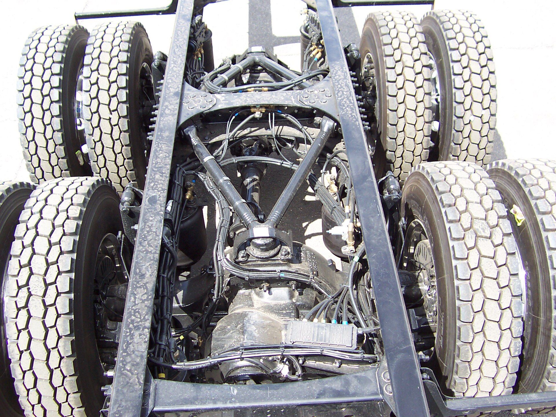
A tractor unit’s specification sheet gives the rear axle two lines: a type, and a number. The type is a code or a short phrase — single reduction, hub reduction, portal. The number is a bare decimal with no unit attached: 2.31, or 3.70, or 5.41. Between them they set how fast the engine turns at motorway speed, how much torque reaches the tyres on a gradient, and which of the two the vehicle was bought to do. Neither is adjustable afterwards. And unlike most driveline vocabulary, both are defined in EU law, because a European regulation had to name the parts before it could simulate their losses.
The regulation that names the parts
Regulation (EU) 2017/2400 determines the CO2 emissions and fuel consumption of heavy-duty vehicles by simulation rather than by driving them. Article 2(1) applies it, subject to the second paragraph of Article 4, to medium lorries, heavy lorries and heavy buses; that second paragraph disapplies Articles 5 to 23 — the block that reaches the axle provisions of Annex VII — to heavy lorries of vehicle groups 6, 7, 8, 13, 14, 15, 17, 18 and 19, to medium lorries of groups 51, 52, 55 and 56, and to any vehicle with a driven front axle in groups 11, 12 and 16. Article 2(3) excludes off-road vehicles, special purpose vehicles and off-road special purpose vehicles as defined in Annex I, Part A, points 2.1 to 2.3, of Regulation (EU) 2018/858. Article 9(1) puts the duty on the vehicle manufacturer, which shall determine the CO2 emissions and fuel consumption of each new vehicle, with the exception of new vehicles using vehicle technologies listed in Appendix 1 to Annex III, to be sold, registered or put into service in the Union using the latest available version of the simulation tool; with regard to heavy buses the vehicle manufacturer or interim manufacturer shall use the method set out in Annex I, point (2). For the excepted technologies only the input parameters specified in Table 5 of Annex III are determined, not CO2 emissions and fuel consumption.
A simulation needs a loss figure for every component in the driveline, so the Regulation had to describe the components first. Annex VII, headed “Verifying axle data”, does that for driven axles. Its paragraph 2 opens by stating that the definitions which follow apply for the purposes of that Annex — they are the vocabulary of one certification procedure, not a general legal definition of an axle. Inside that frame they are the only place in EU law where these five words are fixed.
| Code | Name | Definition |
|---|---|---|
| SR | Single reduction axle | A driven axle with only one gear reduction, typically a bevel gear set with or without hypoid offset. |
| SP | Single portal axle | An axle that has typically a vertical offset between the rotating axis of the crown gear and the rotating axis of the wheel due to the demand of a higher ground clearance or a lowered floor to allow a low floor concept for inner city buses; typically the first reduction is a bevel gear set, the second a spur gear set (or helical gear set) with vertical offset close to the wheels. |
| HR | Hub reduction axle | A driven axle with two gear reductions: the first typically a bevel gear set with or without hypoid offset, the other a planetary gear set typically placed in the area of the wheel hubs. |
| SRT | Single reduction tandem axle | Basically similar to a single driven axle, but also transfers torque from the input flange over an output flange to a further axle. |
| HRT | Hub reduction tandem axle | A hub reduction axle with the possibility to transfer torque to the rear as described for the SRT. |
What the number counts
The ratio is a multiplier between the shaft and the wheel, and the Regulation uses it as one. Annex VII calculates the efficiency of each measured grid point from output torque, input torque and iaxle, the axle ratio; Appendix 3 to the same Annex calculates the basic drag torque on the wheel side as Td0 = T0 + T1 × igear. Torque is multiplied by the ratio on the way out; shaft speed is divided by it. That is the whole of what the decimal means.
Appendix 2 shows how tightly it is pinned. The axle information document asks the manufacturer to declare the axle line as SR, HR, SP, SRT or HRT, then the axle gear ratio, then the crown wheel diameter, the vertical offset between pinion and crown wheel, the teeth number of pinion and the teeth number of crown gear. The ratio is declared alongside the tooth counts that produce it, not as a rating, and the drawing behind it sits with the approval authority.
Volvo publishes the practical consequence. Its RSS1370A, a hypoid single-reduction solo axle rated to 13 tonnes on the axle and 70 tonnes gross combination weight, is listed on its fact sheet at 2.06, 2.17, 2.31, 2.47, 2.64, 2.85 and 3.08:1. Between the 2.31 and the 2.85 there is a 23 percent difference in propeller shaft speed at any given wheel speed — that percentage is our arithmetic from the two published ratios, not a Volvo figure. What the sheet does not give is an engine: it describes the axle as designed for an electric drive unit torque of 3550 Nm, its specification line reads a maximum electric drive unit torque of 3500 Nm, and no engine torque appears anywhere on it. The ratio is a shaft-to-wheel figure, and that is as far as the document licenses it to be read. Vehicle makers reach for the same tall end of that list from the other direction: the Model Year 24 brochure for the Iveco S-Way advertises new rear axle ratios of 2.17 and 2.06 among its fuel-consumption measures, the same two numbers the Volvo fact sheet carries, and the Ford Trucks F-MAX data sheet puts 2.31 against its standard variants and 2.17 against the low-coupling one.
Where the reduction happens, and what it does not settle
Put two Volvo axles of the same axle load and combination weight side by side and the effect of a second reduction shows in the hardware. The single-reduction RSS1370A runs 2.06 to 3.08:1 with a 485 mm crown wheel. The RSH1370F, a solo axle with hub reduction rated to the same 13 tonnes on the axle and 70 tonnes gross combination weight, carries a crown wheel of 295 mm and is listed ratio by model: 3.46, 3.61, 3.76, 4.12 and 4.55:1 on the FE, FH and FM; 5.41:1 on the FH and FM; and 4.67, 5.46, 6.18 and 7.21:1 on the FE alone. On those two fact sheets the hub-reduction axle’s lowest ratio sits above the single-reduction axle’s highest. Only the weights are shared, though: the RSH1370F sheet gives a maximum engine torque of 3550 Nm, where the RSS1370A’s rates the axle against an electric drive unit. Volvo’s own explanation of the centre gear is that the major part of the reduction gearing takes place in the hub gears and only a small portion in the centre gears, which leaves a small diameter difference between pinion and crown wheel and a service-friendly centre gear with low drive losses. Reading the 485 mm and the 295 mm as the visible consequence of that is ours; Volvo prints the two diameters on separate fact sheets and draws no comparison between them.
Widen the frame past those two sheets and the pattern stops holding, because Volvo’s own model pages disagree with them. On a construction chassis the two families sit side by side in one table: the Volvo FMX specification sorts its rear axles into a single-reduction group and a hub-reduction group, with approved combination weights running from 44 tonnes on the RSS1344C/E to 150 tonnes on the RTH3815. That page’s rear axle ratio table gives the RSS1370A/B 2.47, 2.64, 2.85, 3.08, 3.40, 3.67 and 4.11:1 — neither end of it matching the fact sheet’s 2.06 to 3.08:1, and its top ratio sitting above the RSH1370F’s lowest of 3.46. Its torque column disagrees as well, giving 3800 Nm for both axles against the RSH1370F fact sheet’s 3550 Nm. The same table lists the single-reduction RSS1344C/E as high as 5.29:1 and the single-reduction tandem RTS2310A as high as 4.63:1, both above every hub-reduction ratio the FMX offers on the RSH1365. Where the reduction happens is not what fixes where the ratio lands; the published ranges overlap, and Volvo has not reconciled its two documents. This page prints both rather than picking one.
The Regulation sorts the lines by ratio as well, though not in order to describe them. Table 2 of Annex VII, under point 6.4, sets the drag-torque tolerance in Nm that a sample may exceed its approved axle by at conformity of production, and bands that tolerance by gear ratio, with the boundary set by axle line: i ≤ 3 or > 3 for SR and SRT, ≤ 6 or > 6 for SP, ≤ 7 or > 7 for HR and HRT. The boundary is a step in a tolerance table rather than the edge of a line’s ratio range, and it is set higher for the hub-reduction lines than for the single-reduction ones. Paragraph 3 of the Annex adds the manufacturing consequence: different axle ratios of hub reduction, hub reduction tandem and single portal axles — HR, HRT and SP — may be measured by exchanging the hub reduction only.
The portal axle exists for ground clearance or a low floor
Paragraph 2(2) is the definition to quote, and it is unusual in tying a mechanical layout to a vehicle concept. A single portal axle means an axle that has typically a vertical offset between the rotating axis of the crown gear and the rotating axis of the wheel “due to the demand of a higher ground clearance or a lowered floor to allow a low floor concept for inner city buses”. An amendment added the construction: typically the first reduction is a bevel gear set, the second a spur gear set — or helical gear set — with vertical offset close to the wheels.
Two things follow. The offset is the purpose of the axle rather than a side effect of it — the Regulation names higher ground clearance or a lowered floor as the demand that produces the layout, and the second of those is what makes a low-floor city bus possible over its driven axle. And the Regulation treats portal axles as a special case throughout. Appendix 2 has a line used for portal axles only, the angle between the pinion axle and the crown wheel axle in degrees. Appendix 4 carries two portal-only family criteria — pinion angle to the horizontal within ± 5°, angle between pinion and crown wheel axles within ± 3.5° — and exempts single portal axles from the axle-housing geometry criterion that binds every other line.
Solaris specifies the drive axle of the Urbino 12 electric with modular drive as a portal axle with stabiliser, driven by a central 240 kW electric motor, on a bus of 19,500 kg gross vehicle weight — up to 20,000 kg depending on country and tyres. It is the layout that lets a battery-electric city bus hold its low floor across the driven axle.
A tandem is two components, not one
The last two definitions describe a drive-through. An SRT is a single-reduction axle that also transfers torque from its input flange over an output flange to a further axle; an HRT is a hub-reduction axle with the same ability. That drive-through is what separates a 6×4 from a 6×2, and the axle configuration notation records only that two axles are driven, never how the torque gets to the second one.
The Regulation accounts for the pair rather than the unit. Appendix 3 states that tandem axles shall be calculated using a combined efficiency for an axle including drive-through, SRT or HRT, plus the matching single axle, SR or HR. Volvo’s RTH3312 shows the hardware: two spiral-bevel single-gear units with hub reduction, a distribution gearbox of cylindrical spur type in the forward rear axle with a ratio of 1:1, three differential locks, ratios from 3.61 to 7.21:1, a maximum bogie loading of 33,000 kg and a maximum combination weight of 120,000 kg. The distribution gearbox does no reduction at all; the number on the specification sheet is still the hub-reduction ratio. Combination weights of that order are a manufacturer’s driveline rating rather than anything a member state will let you run on a plate alone.
What the law assumes when nobody measures the axle
An axle family can be certified by measurement, or the manufacturer can accept the standard values in Appendix 3 to Annex VII. Those values are a generic efficiency for the load-dependent losses plus a generic basic drag torque, and they are set per axle line.
| Basic function | Generic efficiency η | Drag torque, wheel side: Td0 = T0 + T1 × igear |
|---|---|---|
| Single reduction axle (SR) | 0.98 | T0 = 70 Nm, T1 = 20 Nm |
| Single reduction tandem (SRT) / single portal (SP) | 0.96 | T0 = 80 Nm, T1 = 20 Nm |
| Hub reduction axle (HR) | 0.97 | T0 = 70 Nm, T1 = 20 Nm |
| Hub reduction tandem axle (HRT) | 0.95 | T0 = 90 Nm, T1 = 20 Nm |
| All other axle technologies | 0.90 | T0 = 150 Nm, T1 = 50 Nm |
Two readings are worth taking from that table. The first is the cost of not being one of the five named lines: an axle that fits none of them is assumed to be 0.90 efficient with a basic drag torque of 150 + 50 × i Nm, against 0.98 and 70 + 20 × i Nm for a plain single-reduction axle. Neither pair of numbers is itself a drag torque — they are the coefficients T0 and T1, and the drag torque is what the formula returns from them. The second reading follows from that: the drag figure grows with the ratio, and nothing else in the table does. Applying the Regulation’s own formula to the ratios above, a single-reduction axle at 2.31 gets a basic drag torque of 116.2 Nm and a hub-reduction axle at 5.41 gets 178.2 Nm — our arithmetic from Table 1 and the published ratios, not numbers printed in the Regulation. It is worth being exact about what that comparison moves, because it moves two things at once. The efficiency column is keyed to the axle line and not to the ratio: every SR axle is scored 0.98 whatever number it carries, and the drop to 0.97, 0.96 or 0.95 comes from being an HR, an SRT or SP, or an HRT. Only Td0 answers to igear. So a numerically higher ratio is penalised on drag alone; the second penalty in the example belongs to the change of line, not to the change of number.
A separate appendix decides which axle in a family gets tested. Under Appendix 4, the parent axle is the one with the highest axle ratio; where more than two axles share that ratio, the manufacturer must submit an analysis identifying the worst-case axle.
Where the number surfaces on paper
Annex IV sets out the files the simulation produces. In the manufacturer’s records file, point 1.7.4 is the axle type — the model gives “single reduction axle” as its own example — and point 1.7.5 is the axle ratio. In the customer information file, the short document that reaches the buyer, the whole driveline is reduced to a handful of entries: transmission values measured or standard, transmission type, number of gears, retarder yes or no, and at point 1.2.8, axle ratio. Of everything in the driveline, the ratio is one of the few facts the paperwork guarantees a buyer will be told.
It is a figure to read against the gearbox rather than alone. Annex IV spells the relationship out where it describes an integrated electric powertrain: the lowest total transmission ratio is the highest gear times the axle ratio, where an axle ratio applies at all. A direct-drive top gear and an overdrive top gear therefore arrive at the same road speed on different axle numbers — the trade-off set out in automated manual transmissions. Volvo’s RSS1344C makes the point about availability rather than theory: 3.70:1 is offered on both the FM and the FH, 4.11 and 4.63:1 on the FM only, and 5.29:1 on the FM in 4×2 alone. That sheet, like the RSS1370A’s, is written around an electric drive unit torque — 2600 Nm — and names no engine. A ratio that suits the route is not always a ratio the model list carries.
Specify it from the work rather than from the list. Decide the loaded gradient the vehicle has to restart on and the speed it will spend its hours at, pick the axle line that reaches both, then choose the ratio inside it. The power and torque figures in the brochure will not tell you which of those two vehicles you are buying; the two lines under “rear axle” will.
Quick answers
- What does a 2.31 axle ratio mean on a truck?
- It is the reduction the final drive applies between the propeller shaft and the wheels. The RSS1370A fact sheet lists that Volvo single-reduction axle at 2.06, 2.17, 2.31, 2.47, 2.64, 2.85 and 3.08:1, and the lower the number the more slowly the propeller shaft turns at a given wheel speed. Volvo's FMX specification table gives the same designation a different list, 2.47 to 4.11:1.
- What is the difference between a single reduction and a hub reduction axle?
- The number of gear reductions. Regulation (EU) 2017/2400, Annex VII paragraph 2(1) defines a single reduction axle as a driven axle with only one gear reduction, typically a bevel gear set with or without hypoid offset; paragraph 2(3) defines a hub reduction axle as a driven axle with two gear reductions, the second a planetary gear set typically placed in the area of the wheel hubs.
- What is a portal axle on a city bus?
- Annex VII paragraph 2(2) of Regulation (EU) 2017/2400 defines a single portal axle as one that has typically a vertical offset between the rotating axis of the crown gear and the rotating axis of the wheel, due to the demand of a higher ground clearance or a lowered floor to allow a low floor concept for inner city buses. Solaris lists exactly that — a portal drive axle — on the Urbino 12 electric with modular drive.
- Why are hub reduction axle ratios numerically higher?
- Not as a rule, only on the pair usually compared. Volvo's fact sheets give 2.06 to 3.08:1 for the RSS1370A single-reduction axle and 3.46 to 7.21:1 for the RSH1370F hub-reduction axle, both rated to 13 tonnes on the axle and 70 tonnes combination weight. But Volvo's FMX specification lists the single-reduction RSS1344C/E up to 5.29:1 and the single-reduction tandem RTS2310A up to 4.63:1, above the RSH1370F's lowest of 3.46:1, so the two published ranges overlap. What splitting the reduction over two stages does is let a high total ratio be carried on a small crown wheel: 295 mm on the RSH1370F against 485 mm on the RSS1370A.
- Where is the axle ratio recorded on a new heavy vehicle?
- In the CO2 documentation the manufacturer has to produce. Annex IV of Regulation (EU) 2017/2400 puts axle type at point 1.7.4 and axle ratio at 1.7.5 of the manufacturer's records file, and repeats axle ratio at point 1.2.8 of the customer information file the buyer receives.
Sources
- Commission Regulation (EU) 2017/2400 on the determination of CO2 emissions and fuel consumption of heavy-duty vehicles (consolidated text, 1 January 2026) — EUR-Lex, Publications Office of the European Union
- Fact sheet — RSS1370A rear single reduction axle, axle load 13 tonnes, GCW 70 tonnes — Volvo Trucks
- Fact sheet — RSH1370F rear hub reduction solo axle — Volvo Trucks
- Fact sheet — RTH3312 rear hub reduction tandem axle — Volvo Trucks
- Fact sheet — RSS1344C rear single reduction axle, axle load 13 tonnes, GCW 44 tonnes — Volvo Trucks
- Solaris Urbino 12 electric with modular drive — technical data — Solaris Bus & Coach
- Volvo FMX specifications — engines, gearboxes, rear axles, chassis — Volvo Trucks
- IVECO S-Way eBrochure (publication H2331001MASTER, 02/24) — IVECO