Drawbar couplings and drawbar eyes: UN R55 classes, the D, Dc, S and V values, and US pintle hooks
UN Regulation No 55 sorts truck and trailer couplings into classes: C with a 50 mm pin, D drawbar eyes, K hooks with L eyes, T and W. What D, Dc, S and V mean, and the US rule.
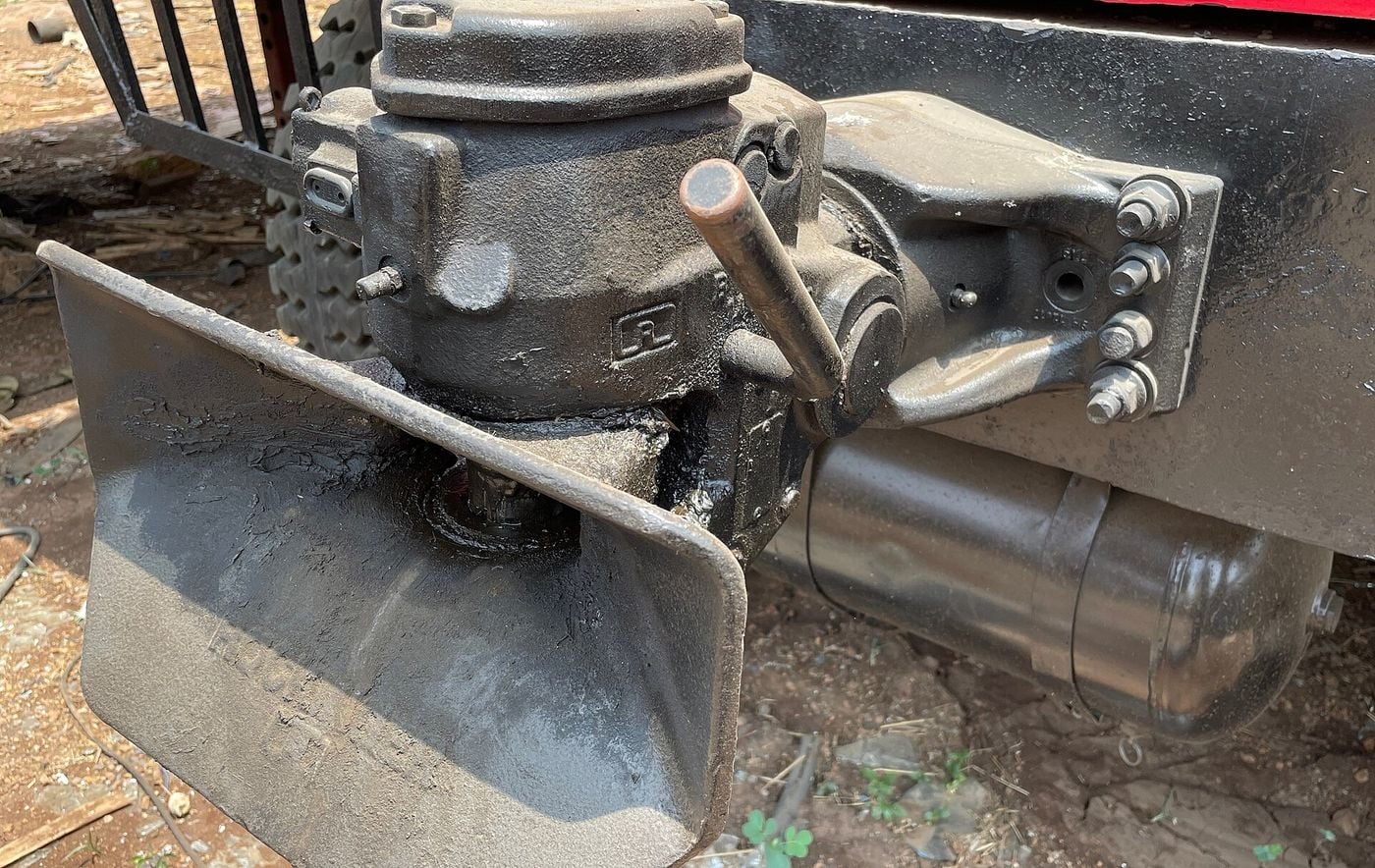
A drawbar coupling and a drawbar eye are the two halves of the connection between a towing vehicle and a trailer with a drawbar. In UN Regulation No 55, the text EU type-approval refers to, a Class C drawbar coupling is the part on the towing vehicle, with a 50 mm diameter pin, a jaw and an automatic closing and locking pin, and a Class D drawbar eye is the part fitted to the trailer’s drawbar, with a parallel hole for that 50 mm pin. The same Regulation sets Class E for drawbars, Class K for hook couplings used with Class L toroidal eyes, and two classes approved as matched pairs, T and W. Each coupling device is marked with its class and, unless the Regulation’s classification already defines them, with characteristic values, the D, Dc, S and V values, that indicate its capacity. On trailers with a maximum technically permissible mass greater than 3.5 tonnes, only couplings that allow automatic coupling are allowed, Class T excepted. In the United States, 49 CFR 393.70 sets the federal rule for tow-bars, pintle hooks and safety chains.
Status as at 14 November 2026. Read on that day: UN Regulation No 55 in the English text published in the Official Journal of the European Union, L 153 of 15 June 2018, which incorporates all valid text up to Supplement 7 to the 01 series of amendments, whose date of entry into force is 10 February 2018, in its web version and, for the formulas of Annex 8, in its PDF; the consolidated text of Regulation (EU) 2019/2144 of 2 August 2026; 49 CFR 393.70 in the annual edition of the Code of Federal Regulations revised as of 1 October 2025; and the product pages of JOST for ROCKINGER and of Ringfeder. The Official Journal copy states that “Only the original UN/ECE texts have legal effect under international public law”. Later supplements and later series of amendments to UN Regulation No 55 were not read.
The version EU type-approval refers to
Article 4(2) of Regulation (EU) 2019/2144 provides that “Type-approval in accordance with the UN Regulations listed in Annex I shall be considered as EU type-approval”. Annex I lists UN Regulation No 55, “Mechanical coupling components of combinations of vehicles”, in its 01 series of amendments as published in OJ L 153, 15.6.2018, p. 179, for vehicle categories M, N and O. Annex II, row F12 “Mechanical couplings”, names UN Regulations No 55 and No 102; for categories M1 to N3 it carries the footnote “Compliance is required if fitted”, and for the trailer categories O1 to O4 it carries no footnote. UN Regulation No 102 was not read. The trailer categories are explained in vehicle categories M, N and O.
UN Regulation No 55 applies to devices and components for motor vehicles and trailers intended to form combinations of vehicles, and for articulated vehicles where the vertical load imposed on the motor vehicle by the trailer does not exceed 200 kN (paragraph 1.2). A dolly is defined there as “a towing trailer designed for the sole purpose to tow a semi-trailer” (paragraph 1.2.1.1).
The coupling classes
Paragraph 2.6 classifies mechanical coupling devices and components by type. Standard devices “are interchangeable within their class, independent of manufacturer” (paragraph 2.3). Non-standard devices, such as Classes C50-X and D50-X, do not conform in all respects to the standard dimensions and characteristic values but can be connected to standard devices of the relevant class (paragraph 2.4). Non-standard miscellaneous devices cannot be connected to standard devices (paragraph 2.5).
| Class | What it is | Types |
|---|---|---|
| A | Coupling balls with a 50 mm diameter spherical device and towing brackets on the towing vehicle | A50-1 to A50-5 standard; A50-X |
| B | Coupling heads fitted to the drawbar of trailers, for the 50 mm coupling ball | B50-X |
| C | Clevis type drawbar couplings on the towing vehicle, with a 50 mm diameter pin, a jaw and an automatic closing and locking pin | C50-1 to C50-7 standard; C50-X |
| D | Drawbar eyes fitted to the drawbar of trailers, with a parallel hole for a 50 mm diameter pin, for automatic drawbar couplings | D50-A welded, D50-B threaded, D50-C and D50-D bolted attachment, all standard; D50-X |
| E | Drawbars, including overrun devices, mounted on the front of the towed vehicle or to its chassis, that are separate units | Non-standard |
| F | Draw beams between the coupling device and the frame, load-bearing bodywork or chassis of the towing vehicle | Non-standard |
| K | Hook type couplings for Class L toroidal drawbar eyes | K1 to K4 non-automatic, KA1 to KA3 automatic, all standard |
| L | Toroidal drawbar eyes for Class K hook couplings | L1 to L5 standard |
| S | Devices not conforming to Classes A to L, T or W, for special heavy transport or unique to some countries and covered by existing national standards | — |
| T | Non-automatic dedicated drawbar couplings, separable only with tools, typically for trailers of car transporters | Non-standard, approved as a matched pair |
| W | Automatic clevis drawbar coupling with its adapted trailer part and an integrated automated electric and pneumatic connector | Non-standard miscellaneous, approved as a matched pair |
The fifth wheel coupling of a tractor and the kingpin of a semi-trailer, Classes G and H, and their D value are covered in kingpin and fifth wheel. The type-approval codes for drawbar trailers, centre-axle trailers and rigid drawbar trailers are in the truck and bus glossary.
Automatic coupling above 3.5 tonnes
Paragraph 4.3 reads: “With the exception of Class T couplings only devices which allow automatic coupling shall be allowed for the coupling of trailers having a maximum technically permissible mass greater than 3,5 tonnes.” The same paragraph requires that coupling and uncoupling be possible by one person without the use of tools.
Paragraph 2.2 defines the requirement. It “is achieved if reversing the towing vehicle against the trailer is sufficient to engage the coupling completely, to lock it automatically and to indicate proper engagement of the locking devices without any external intervention”. For hook couplings it is achieved if opening and closing of the locking device takes place without any external intervention when the drawbar eye is inserted into the hook. Annex 5, paragraph 10.1.2, makes the hook couplings K1 to K4 non-automatic couplings for use only on trailers not exceeding 3.5 tonnes maximum permissible mass, and KA1 to KA3 automatic.
Other general requirements in paragraph 4: all parts whose failure could result in separation of the vehicle and trailer shall be made of steel, unless the manufacturer demonstrates the equivalence of another material (paragraph 4.2), and every device shall have positive mechanical engagement, with the closed position locked at least once by further positive mechanical engagement unless Annex 5 states further requirements (paragraph 4.5). For Class C drawbar couplings, Annex 5 requires two such locking devices in the closed position, “each of which shall remain effective should the other fail”, and a mechanical indicator of the closed and locked position whose position can be verified “by feel, for example, in the dark” (paragraph 3.5).
Devices for remote indication and remote control are permitted only on automatic coupling devices of Classes C50-X and G50-X (Annex 5, paragraph 13.1). A remote indicator shows the change to the closed and doubly locked position by a green optical signal; if the open or unlocked position is shown, a red signal is used (paragraphs 13.2.2 and 13.2.3).
Class C couplings and Class D drawbar eyes
Class C50 drawbar couplings “shall be compatible with all Class D50 drawbar eyes and couplings with the specified characteristics” (Annex 5, paragraph 3.2). Their jaw guides the drawbar eye into the coupling, and its minimum size depends on the D value: 150 mm wide and 100 mm high up to 18 kN, 280 by 170 mm above 18 kN up to 25 kN, and 360 by 200 mm above 25 kN; smaller jaws are permitted for Class C50-X drawbar couplings only under the conditions the same paragraph sets (paragraph 3.3). Coupled to the drawbar coupling but not fitted to a vehicle, the drawbar eye shall be able to move at least ±90° horizontally, ±20° vertically and ±25° in axial rotation (paragraph 3.4). On the standard Classes C50-1 to C50-6 the swivel of the eye about the transverse axis comes from the spherical shape of the coupling pin, and longitudinal shock loads are attenuated by spring or damping devices, except on Class C50-1 (paragraph 3.7).
Class D50 drawbar eyes are intended for use with C50 drawbar couplings and “shall not be able to rotate axially (because the respective couplings can rotate)” (Annex 5, paragraph 4.1). Standard drawbar eyes and their means of attachment are tested for the load values of Table 7 (paragraph 4.3).
| Class | D | Dc | S | V |
|---|---|---|---|---|
| C50-1 | 18 | 18 | 200 | 12 |
| C50-2 | 25 | 25 | 250 | 10 |
| C50-3 | 70 | 50 | 650 | 18 |
| C50-4 | 100 | 70 | 900 | 25 |
| C50-5 | 130 | 90 | 1,000 | 35 |
| C50-6 | 190 | 120 | 1,000 | 50 |
| C50-7 | 190 | 130 | 1,000 | 75 |
| D50-A | 130 | 90 | 1,000 | 30 |
| D50-B | 130 | 90 | 1,000 | 25 |
| D50-C | 190 | 120 | 1,000 | 50 |
| D50-D | 190 | 130 | 1,000 | 75 |
Hook couplings and toroidal eyes: Classes K and L
A Class K hook coupling “shall only be used with a toroidal drawbar eye” (Annex 5, paragraph 10.1.3), and Class L toroidal eyes are intended for use with Class K couplings (paragraph 4.4.1). Automatic Class K couplings have a jaw that guides the eye into the coupling, and in the closed position every Class K coupling is locked by two positive mechanical engagement locking devices, with a mechanical indicator, as on Class C (paragraphs 10.3 and 10.4).
| Class | D | Dc | S | V |
|---|---|---|---|---|
| K1 | 17 | — | 120 | — |
| K2 | 20 | — | 120 | — |
| K3 | 20 | 17 | 200 | 10 |
| K4 | 25 | 20 | 250 | 10 |
| KA1 | 70 | 54 | 700 | 18 |
| KA2 | 100 | 70 | 900 | 25 |
| KA3 | 130 | 90 | 1,000 | 35 |
| L1 | 30 | 27 | 200 | 12 |
| L2 | 70 | 54 | 700 | 18 |
| L3 | 100 | 70 | 950 | 25 |
| L4 | 130 | 90 | 1,000 | 35 |
| L5 | 180 | 120 | 1,000 | 50 |
Drawbars: Class E
Class E covers non-standard drawbars, including overrun devices, mounted on the front of the towed vehicle or to its chassis, which couple to the towing vehicle by drawbar eyes, coupling heads or similar devices (paragraph 2.6.5). A drawbar may be hinged, free to move in a vertical plane and supporting no vertical load, or rigid, fixed in a vertical plane so as to support a vertical load; it may comprise more than one component and be adjustable or cranked. The Regulation applies to drawbars “which are separate units, not an integral part of the chassis of the towed vehicle”.
Drawbars may carry coupling heads or drawbar eyes, attached by screwing, bolting or welding (Annex 5, paragraph 5.2). Hinged drawbars shall have height adjusting devices that one person can operate without tools, with a range of at least 300 mm up and down from the horizontal (paragraphs 5.3.1 and 5.3.2), and they are marked with an additional value, Av, the maximum permitted axle mass in tonnes of the front steered axle group of a full trailer (paragraph 2.11.5 and Annex 4). Lengths and weights of the truck and drawbar trailer combination are covered in box trucks and rigid distribution trucks.
Classes T and W
Class T couplings are “intended for use on specific vehicle combinations, for example, car transporters”, whose special structures may need an unusual location of the coupling (Annex 5, paragraph 11.1). They are restricted to use with centre-axle trailers, approved as a matched pair, and “it shall not be possible to separate the coupling other than in a workshop using tools which are not normally carried on the vehicle”; they shall not be automatic in operation (paragraphs 11.2 to 11.4). They are the one exception to the automatic coupling rule of paragraph 4.3. The car transporter combinations themselves are described in car transporter trucks and trailers.
Class W couplings make the electric and pneumatic braking connection as well as the mechanical one. As part of an automated sequence of actions they “automatically mechanically connect the two vehicles and establish the electric and pneumatic braking transmission connection”, and in the reverse sequence they break that connection and disconnect the vehicles (Annex 5, paragraphs 12.1.1 and 12.1.2). Both mechanical parts are approved as a matched pair (paragraph 2.6.14), and a Class W coupling shall have a remote indication (paragraph 12.5). The air and electric connections between truck and trailer are the subject of trailer braking systems.
The values on the coupling: D, Dc, S, V and Av
Paragraph 2.11 defines the characteristic values:
- D and Dc are “characteristic performance values for the horizontal forces of the coupling equipment”; Dc is the D value for centre-axle trailer applications. Both are in kN.
- S is “the vertically imposed mass, in kilograms, to the coupling from a centre axle trailer under static conditions”.
- V is “the amplitude of the vertical force imposed on the coupling by a centre axle trailer”, in kN.
- Av, for hinged drawbars, is the maximum permitted axle mass in tonnes of the front steered axle group of a full trailer.
A centre-axle trailer, in paragraph 2.13, has a drawbar which cannot move in a vertical plane independent of the trailer and axles close to its centre of gravity; the vertical load it imposes on the towing vehicle’s coupling “shall not exceed 10 per cent of the maximum mass of the trailer, or 1 000 kg, whichever is the lesser”.
Every mechanical coupling device or component is marked with its class and with its characteristic values to indicate its capacity (Annex 4, point 1), adjacent to the approval mark (paragraph 7.3). The characteristic values need not be marked where the classification in the Regulation defines them, for example for Classes A50-1 to A50-5 (paragraph 7.3). In the example of Annex 4, the marking “C50-X D130 Dc90 S1000 V35” identifies a non-standard drawbar coupling of Class C50-X with a maximum D value of 130 kN, a maximum permitted Dc value of 90 kN, a maximum permitted static vertical imposed mass of 1,000 kg and a maximum permitted V value of 35 kN.
Annex 8 sets out how the values a vehicle combination requires are calculated. Its acceptance criteria are fulfilled if the calculated values “are not higher than the characteristic performance values of the coupling equipment” (Annex 8, paragraph 1.1(a)) or, for a drawbar coupling that does not meet that, if the calculated values and the limiting V value specified by the vehicle manufacturer meet all the criteria of paragraph 4 of the Annex (paragraph 1.1(b)). For two-vehicle combinations, paragraph 2.1 gives:
- for coupling devices not designed to support imposed vertical loads: D = g · T · R / (T + R), in kN;
- for coupling devices for centre-axle trailers: Dc = g · T · C / (T + C), in kN.
T is the technically permissible maximum mass of the towing vehicle in tonnes, including, where relevant, the vertical load imposed by a centre-axle trailer; R is the technically permissible maximum mass in tonnes of a trailer with drawbar free to move in a vertical plane; C is the mass in tonnes transmitted to the ground by the axle or axles of the centre-axle trailer when coupled and loaded to its technically permissible maximum mass (Annex 8, paragraph 2.1); and g is 9.81 m/s² (paragraph 2.12). For centre-axle trailers with a technically permissible maximum mass greater than 3.5 tonnes, paragraph 2.2 gives V = a · C · X² / L², in kN, where a is 1.8 m/s² for air suspension on the rear axle of the towing vehicle, or suspension with equivalent damping, and 2.4 m/s² for other suspension; X is the length of the trailer’s loading area and L the distance from the centre of the drawbar eye to the centre of the axle assembly, both in metres; X² / L² is taken as at least 1.0. Paragraph 2.1 also gives a formula for fifth wheel couplings of Classes G, H and J; the D value of the fifth wheel is covered in kingpin and fifth wheel.
United States: tow-bars, pintle hooks and safety devices
In the Federal Motor Carrier Safety Regulations, coupling devices are covered by 49 CFR 393.70, “Coupling devices and towing methods, except for driveaway-towaway operations”. Paragraph (a) requires that, on a level, smooth, paved surface in a straight line, the path of the towed vehicle “will not deviate more than 3 inches to either side of the path of the vehicle that tows it”.
Paragraph (c) covers the towing of full trailers. “A full trailer must be equipped with a tow-bar and a means of attaching the tow-bar to the towing and towed vehicles.” The tow-bar and its attachment must be structurally adequate for the weight being drawn, properly and securely mounted, provide for adequate articulation without excessive slack, and be provided with a locking device that prevents accidental separation. The paragraph adds: “The mounting of the trailer hitch (pintle hook or equivalent mechanism) on the towing vehicle must include reinforcement or bracing of the frame sufficient to produce strength and rigidity of the frame to prevent its undue distortion.”
Paragraph (d) requires every full trailer, and every converter dolly used to convert a semitrailer to a full trailer, to be coupled to the frame of the towing vehicle, or an extension of it, with one or more safety devices that keep the towed vehicle from breaking loose if the tow-bar fails or becomes disconnected. The safety device “must not be attached to the pintle hook or any other device on the towing vehicle to which the tow-bar is attached”, although, where the pintle hook or other device was manufactured before 1 July 1973, it may be attached at a place on a pintle hook forging or casting that is independent of the pintle hook (paragraph (d)(1)); it must have an ultimate strength “of not less than the gross weight of the vehicle or vehicles being towed” (paragraph (d)(3)); and it must keep the tow-bar from dropping to the ground if it fails or becomes disconnected (paragraph (d)(4)). Where the safety device consists of safety chains or cables, the towed vehicle must be equipped with either two safety chains or cables or a bridle of a single chain or cable attached at two points (paragraph (d)(5)); converter dollies with a solid tongue have their own provision in paragraph (d)(6).
Makers’ own descriptions
JOST sells towing hitches, as it calls them, and drawbars under the ROCKINGER brand. Its product page gives 1875 as the year the master smith Johann Rockinger founded the company, 1927 for the “safety coupling for HGVs”, which it calls the first fully automatic ROCKINGER trailer coupling, and 2001 for the acquisition of ROCKINGER by JOST. In 2004, the page says, JOST took over the drawbar maker Regensburger Zuggabel, whose products are sold under the ROCKINGER brand today. The commercial vehicle range on the page lists towing hitches, hook couplings 76 mm, a ball head hitch 80 mm, ball hitches 50 mm, the VARIOBLOC alternating system, manual towing hitches, traverses, adapter towing hitches and towing eyes, with drawbars as a separate range.
The Ringfeder pages carry the name and Krefeld address of VBG Group Truck Equipment GmbH. Ringfeder’s coupling list groups couplings, tow couplings and hook couplings and filters them by drawbar eye diameter: 25, 40, 50 and 76 mm. In that list, four hook couplings for toroidal drawbar eyes carry the tag “ECE R55-01”. Of its RF50 A/B trailer coupling, Ringfeder writes that it “works with hinged drawbars as well as centre axle trailers with rigids, or dollies with 50 mm drawbar eyes”, and that the coupling is self-closing and automatically secured.
Quick answers
- What is the difference between a drawbar coupling and a drawbar eye?
- In UN Regulation No 55 the drawbar coupling, Class C, sits on the towing vehicle: it has a 50 mm diameter pin, a jaw and an automatic closing and locking pin. The drawbar eye, Class D, is fitted to the drawbar of the trailer and has a parallel hole for that 50 mm pin; the standard eyes are D50-A for welded, D50-B for threaded and D50-C and D50-D for bolted attachment. Class C50 couplings shall be compatible with all Class D50 eyes.
- Does a truck trailer need an automatic coupling?
- Under paragraph 4.3 of UN Regulation No 55, only devices which allow automatic coupling are allowed for coupling trailers with a maximum technically permissible mass greater than 3.5 tonnes, with the exception of Class T couplings. The non-automatic hook couplings K1 to K4 are for trailers not exceeding 3.5 tonnes; KA1 to KA3 are automatic. Automatic coupling means that reversing the towing vehicle against the trailer engages the coupling, locks it and indicates the engagement without any external intervention.
- What do D, Dc, S and V on a trailer coupling mean?
- They are the characteristic values of UN Regulation No 55. D and Dc are values in kN for the horizontal forces, Dc for centre-axle trailers; S is the static vertical mass in kg imposed by a centre-axle trailer; V is a value in kN for the amplitude of the vertical force from a centre-axle trailer. The coupling is marked with its class and these values, for example C50-X D130 Dc90 S1000 V35 on a non-standard Class C50-X drawbar coupling.
- What are the D values of the standard C50 drawbar couplings?
- Table 5 of Annex 5 to UN Regulation No 55 gives minimum D values of 18, 25, 70, 100, 130, 190 and 190 kN for Classes C50-1 to C50-7, Dc values of 18, 25, 50, 70, 90, 120 and 130 kN, S values of 200, 250, 650, 900 and three times 1,000 kg, and V values of 12, 10, 18, 25, 35, 50 and 75 kN.
- What does US federal law require for a pintle hook and safety chains?
- 49 CFR 393.70(c) requires a full trailer to have a tow-bar with a locking device that prevents accidental separation, and the mounting of the trailer hitch (pintle hook or equivalent mechanism) on the towing vehicle must include reinforcement or bracing of the frame. Under 393.70(d) the safety device, such as two safety chains or cables, must not be attached to the pintle hook or any other device to which the tow-bar is attached, except that, for a pintle hook or other device manufactured before 1 July 1973, it may be attached at a place on a pintle hook forging or casting that is independent of the pintle hook, and must have an ultimate strength of not less than the gross weight of the vehicle or vehicles being towed.
Sources
- UN Regulation No 55, uniform provisions concerning the approval of mechanical coupling components of combinations of vehicles [2018/862], incorporating Supplement 7 to the 01 series of amendments (in force 10 February 2018), OJ L 153, 15.6.2018, p. 179 — paragraphs 1 to 4 and 7, Annexes 4, 5 and 8 — Official Journal of the European Union (EUR-Lex), 15 Jun 2018
- Regulation (EU) 2019/2144 on type-approval requirements for motor vehicles and their trailers — consolidated text of 2 August 2026, Article 4(2), Annex I (UN Regulation No 55) and Annex II (row F12) — EUR-Lex, European Union
- 49 CFR 393.70, Coupling devices and towing methods, except for driveaway-towaway operations — Code of Federal Regulations, Title 49, annual edition revised as of 1 October 2025 — Federal Motor Carrier Safety Administration, via govinfo.gov, 1 Oct 2025
- ROCKINGER towing hitches and drawbars — product page (read on 14 November 2026) — JOST-Werke
- Ringfeder couplings: trailer couplings, tow couplings and hook couplings — product list (read on 14 November 2026) — VBG Group Truck Equipment GmbH (Ringfeder)
- Ringfeder trailer coupling RF50 A/B — product page (read on 14 November 2026) — VBG Group Truck Equipment GmbH (Ringfeder)